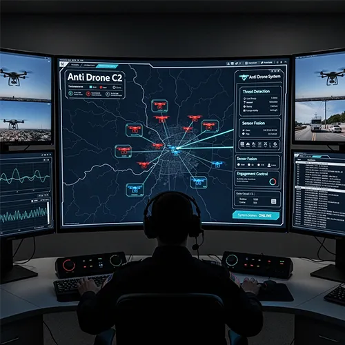
Anti Drone System Command and Control (C2) software
The Anti Drone System – Command and Control (C2) software is the central element that links all components of the anti drone system into a single integrated interface, used to manage detection, tracking, jamming, and interception operations simultaneously, providing field commanders with a unified operational picture.
|
|
|
Anti Drone System Command and Control (C2) software |
|
|
|
Command and Control (C2) software |
|
- Proposed Fusion Assessment Control Engine (FACE) C2 platform is a leader in sensor fusion and correlation. It is currently in use at several airports and many other locations helps to dramatically reduce the manpower burden by significantly reducing false alarm rates, therefore reducing the distraction rate for the operator. |
|
- With our open architecture and ‘any sensor – any effector’ mantra, FACE has the ability to scale quickly to suit the customers’ requirements. |
 |
|
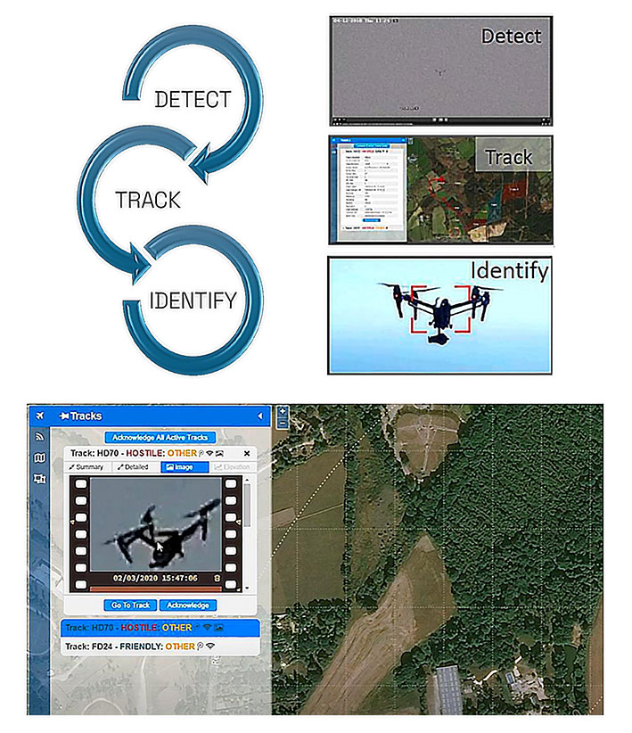
- AI-based imagery is automatically taken and saved for future review - Adding EO/IR solutions allow for absolute evidence of a UAV within sensitive airspace
|
|
RF signals which Anti Drone System detected: |
|
UPLINK signals |
|
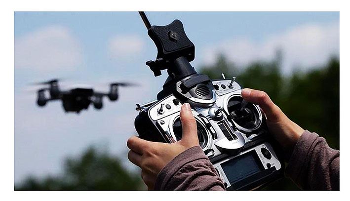
Signals for the drone remote control that can be Wi-Fi, Bluetooth or own signals - most often FHSS (Frequency-hopping spread spectrum) |
|
DOWNLINK signals |
|
Telemetry signals from the drone. Video data (analog PAL/NTSC, Wi-Fi or own protocols (for example Ocusync, DJI Lightbridje, etc). GNSS data for the drone and pilot (for example GPS, Gallieo, GLONASS, Beidou, etc). |
|
Detected Frequency bands: |
|
433 MHz; 915 MHz; 2,4 GHz; 5,8 GHz. Option for wide band detection receiver. |
 |
|
Main mission |
|
- RF detection of the Uplink and Downlink communication links between drones and their remote-control stations - Detection in long distances (up to 10 km) at 360° - Detection of multiple drones simultaneously° in 360 (swarm detection) - Tracking and recording of the detected drones - Historical logs of the detected drones - Jamming of the uplink and downlink communication links between drones and their remote-control stations and jamming of the GNSS signals. |
|
The results are as follows: a) Drone will stop flight and will return to home position (or other predefined position) b) Drone will stop flight and will land at the position where GNSS information is lost, because of the jamming |
|
RF Detection of the drone |
|
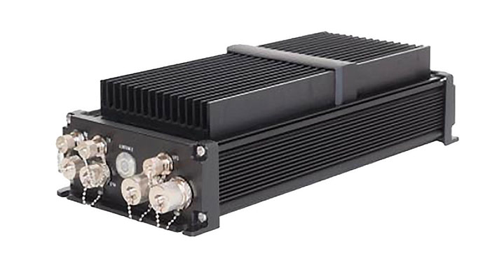
- RF frequency detection in 360° - Detection finding high effective antenna - Range of detection – up to 10 km - Detection time when drone is within range of detection < 1 sec - Highly efficient, low noise architecture - Flexible architecture - Easy deployment in any area - Network connectivity - Passive sensors: a) Do not need to close airspace b) Does not interface with local radio communication c) Does not interface with other sensors - Detection is not depended from size of the drones - Low consumption |
|
Geofence area around guarded zone |
 |
|
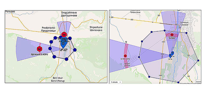
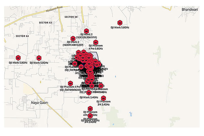
RF Detection of the drone – targets visualization |
|
|
|
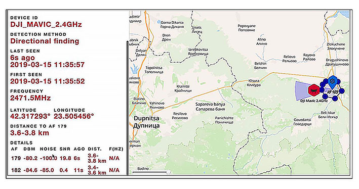
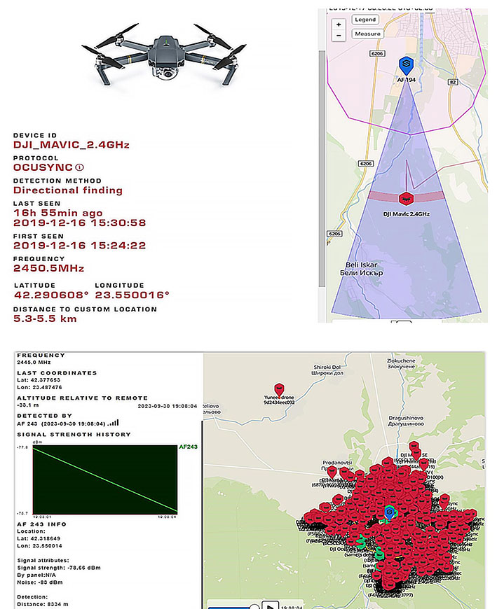
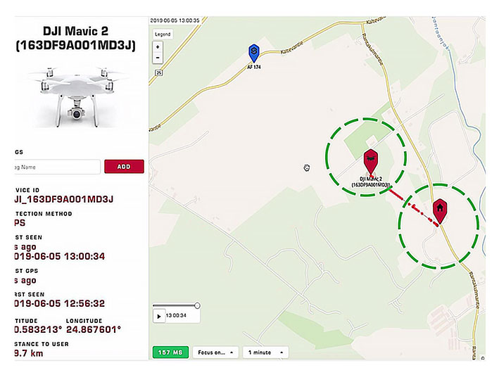
Determination of the drone coordinates, distance, RC working frequency, type (model) of the drone, time for detection |
|
|
|
Tracking of the drone after detection |
|
|
|
Maximum detection distance |
|
|
|
Detection distance |
|
|
|
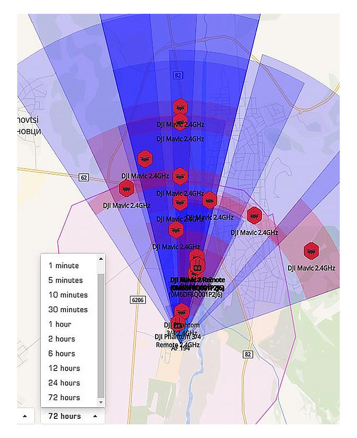
Review of the detected drones in the last 72 hours |
|
|
|
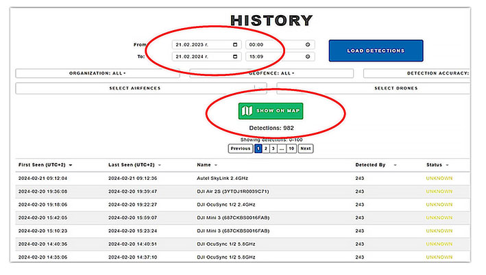
Review of the detected drones in the period of time depending on the requirements |
|
|
|
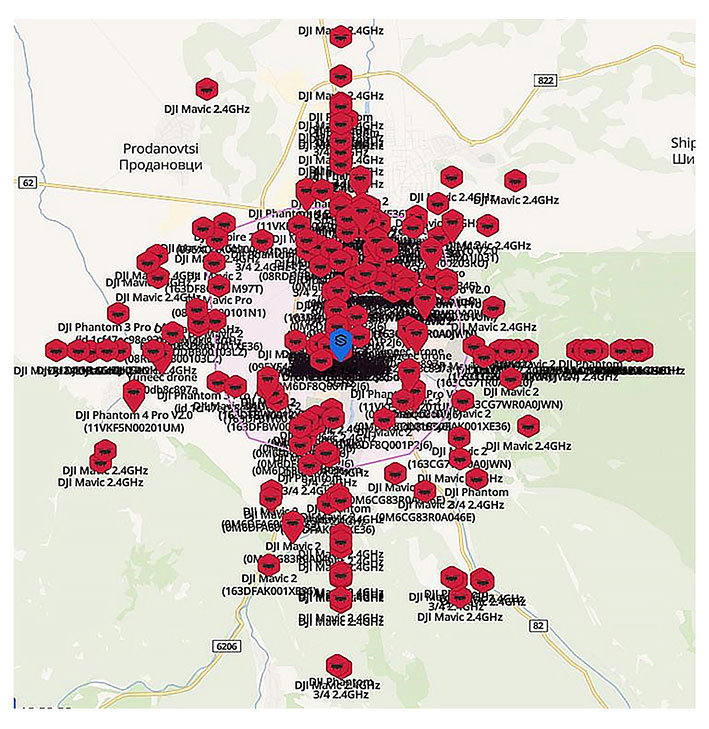
Displaying on the map of the pass detected drones in period of time depending on the requirements |
|
|
|
Displaying on the map of the pass detected drones in period of time depending on the requirements |
|
|
|
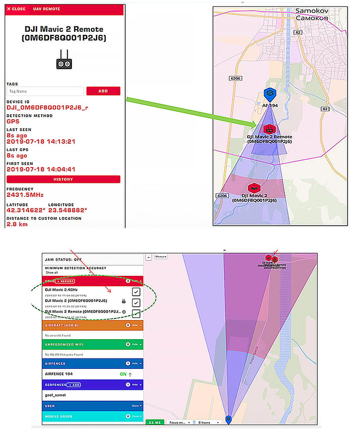
Determination of the drone and pilot location |
|
|
|
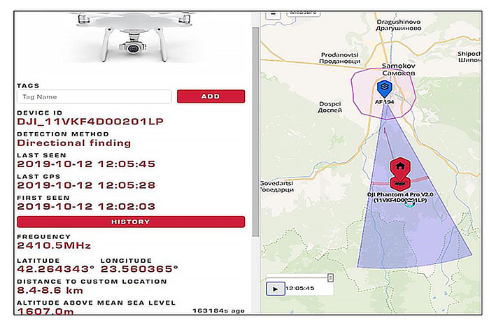
Determination of the drone and its RC serial number |
|
|
|
Determination of the drone and pilot location |
|
|


-001_1782820225.webp)